Sheet metal design consideration dimple.
Minimum distance between two bends sheet metal.
For bends the minimum distance between the inside edge of the bend and the outside of the hem should be 5 times material thickness plus bend radius plus hem radius.
The minimum distance from a weld to a form is the spot diameter plus the bend radius.
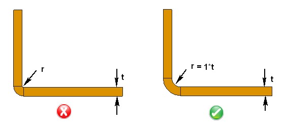
In low carbon steel sheet metal the minimum radius of a bend should be one half the material thickness or 0 80 mm 0 03 inch whichever is larger counterbores.
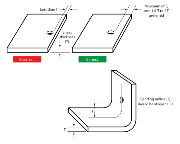
Usually the preferred distance between holes and a bend is 1 5 times the sheet.
Use pems instead of threaded inserts.
Minimum sheet metal bending radius.
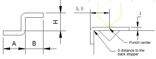
A 7 67 b 0 5 minimum l bending 3 0.
Whenever a increases by 1mm b increases 1 87 accordingly.
The minimum distance between one dimple and another is four times the material thickness plus the inside radius of each dimple.
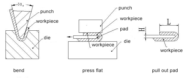
Minimum sheet metal bend radius depends on the selection of tool and the process.
The minimum distance between a weld and the edge is two times the diameter of the spot weld.
The minimum distance between welds is 10 times the material thickness.
For open hem the bend will lose its roundness when the inside diameter is greater than the sheet metal thickness.
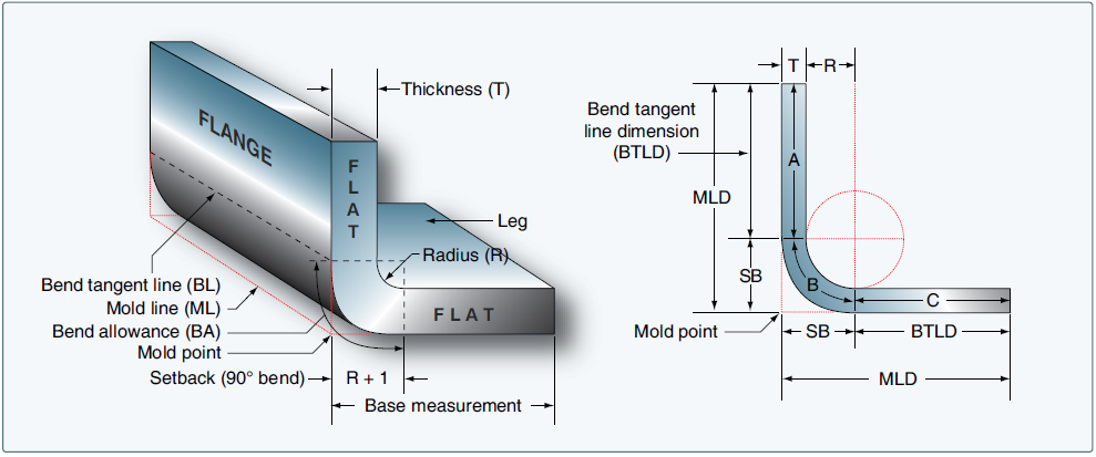
Bend radii minimum bend sizes.
The distance between the sheet metal bend line and edge of the hole should be two times or greater the thickness of the sheet metal.
The sheet metal design rule of thumb in this case is.
Distance from outside mold line to the bottom of the cutout should be equal to the minimum flange length prescribed by the air bend force chart.
3 reduction formula empirical value of gooseneck punch 0 5mm sheet.
Also spaces between pierced holes and bends should accommodate the bend radius h and be far enough from the bend.
Recommended minimum distance between hole slot edge to bend in sheet metal design is three times the sheet thickness plus bend radius.
Center to center distance between two holes minimum center to center distance between two holes in sheet metal parts is required to avoid metal distortion deformation and fracturing.
For bends the minimum distance between the inside edge of the bend and the outside of the hem should be 5 times material thickness plus bend radius plus hem radius.
It is most economical to use a single bend radius throughout the design but if necessary you can utilize multiple radii.
Use this document to choose values that are both manufacturable and meet your needs.
The minimum distance from a counterbore to an edge is four times the material thickness.
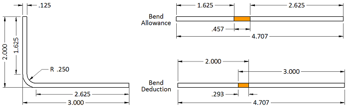
Bending size shown in the following picture.
Using 20 times the material thickness is ideal.
The increasing relation between two sizes the longer a is the longer b is.